KIEL PROBES

GENERAL INFORMATION
Aerodynamic Properties Kiel probes are used to measure total pressure in fluid stream where the direction of flow is unknown or varies with operating conditions. Their correction factor is 0 when used within the ranges outlined below.
Mach Number Range True total pressure is indicated up to a Mach Number of 1.0. There is a slight drop in yaw in sensing range above Mach Number 0.3m. This decreases averages about 4% for all types at a Mach Number of 1.0.
Reynolds Number Range Insensitive to Reynolds Number except at extremely low velocities for Pitot-Static probes. For air this limiting velocity is about 4 ft/sec for the smallest size Kiel probes listed.
Time Constant This depends on the complete installation, probe, pressure lines, and manometer. With 1/8" connecting hose up to 20 ft. long and a liquid manometer of 1/4" ID, the Type B probe will reach equilibrium reading in approximately 15 seconds. Using this time "t" as a standard the other time constants for average stem lengths will be:
Type |
Constant |
A |
2.4t |
C,D,H |
.04t |
E,F |
.02t |
Turbulence Errors Negligible, especially since the probe is yaw insensitive. Very High turbulence may cut down the yaw and pitch insensitive ranges however.

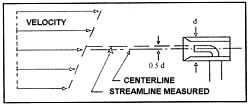
Boundary Effects Boundary effects are small as in all total pressure probes. However, in steep total pressure gradients as near solid boundaries or in "trough" behind guide vanes a shift in the effective center of the probe occurs, so the total pressure measured corresponds to the streamline 0.5d away from the geometrical center of the head in the direction of the higher total pressure as shown in Fig. 3 below.

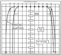
Yaw and Pitch Angle Range The outstanding advantage of Kiel probes compared with other total pressure probes is complete insensitivity to direction of flow within certain limits. Their yaw and pitch characteristics are generally the same although stem interference on some designs will change one from the other. Fig. 1 shows these flow angles and Fig. 2 is a typical calibration curve of a Type A probe. It can be seen that the correction factor equals 0 up to the limits of the yaw range and then drops very sharply. The range is arbitrarily defined as the point where the error equals 1% of velocity pressure. Symbols used in these figures are:
| Pt: Total Pressure | Ps: Static Pressure |
| Ptp: Indicated Total Pressure | |
The yaw and pitch range for all types listed above at a Mach Number of .25 are:
Type |
Yaw Range |
Pitch Range |
A |
±52° |
+47° - 40° |
B |
±48° |
±45° |
C |
±54° |
±49° |
D |
±54° |
±49 |
E |
±63° |
±58° |
F |
±67° |
±61° |
G |
±31° |
±35° |
H |
±35° |
±38° |

Installation These probes are usually installed through holes large enough to pass the head as listed on the Kiel Specification pages. See each individual type for the minimum size.
Special construction including other material, designs to customer's specifications, special take-offs, and mounting adapters quoted as requested.
